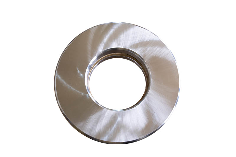
Thrust ball bearings
Thrust ball bearings are separable and their limit rotational speed is low.
Structures:
1.51000 type single-direction thrust ball bearings, this type of bearing can only accommodate axial load on one direction and can control the axial movement on one direction of the shaft and housing.
2.52000 type double-direction thrust ball bearings, this type of bearings can accommodate axial load on double direction and can control the axial movement on double direction of shaft and housing.
3. 560000 type thrust angular-contact ball bearing, as this structure can carry axial load and radial simultaneously.
Cage materials
When the outside diameter is equal or lesser than 250mm, thrust ball bearings generally adopt pressed steel sheet cages, when the outside diameter is more than 250mm,it will adopt solid cages.
Minimum axial load
When the thrust ball bearing is operating, if the applied axial load is too small, the axial direction is not tightly pressed, then acted by centrifugal force, the steel ball will slip and displace and destroy the normal operation of the bearings. To avoid the occurrence of such case, an axial load, Famin must be applied when the thrust ball bearings is working. The calculating formula is:
In the equation, Famin Minimum axial load (kN)
A Minimum load constant
N Revolution (r/min)
Minimum load constant A is showing in the bearings dimension table. If the applied axial load is small, a spring must be used to preload the bearing.
Permissible tilt angle
The double supporting surface of thrust ball bearings should be parallel. The axis center line should be square with shell supporting surface, if this is not assured, it can compensate by adopting spherical housing washer and self-aligning washer.
Tolerance
The tolerance value of thrust ball bearings is showing in the section “the tolerance of rolling bearing”.
Dynamic equivalent axial load
Whenα=90°,thrust ball bearings can only carry axial load and its dynamic equivalent axial load is: Pa=Fa
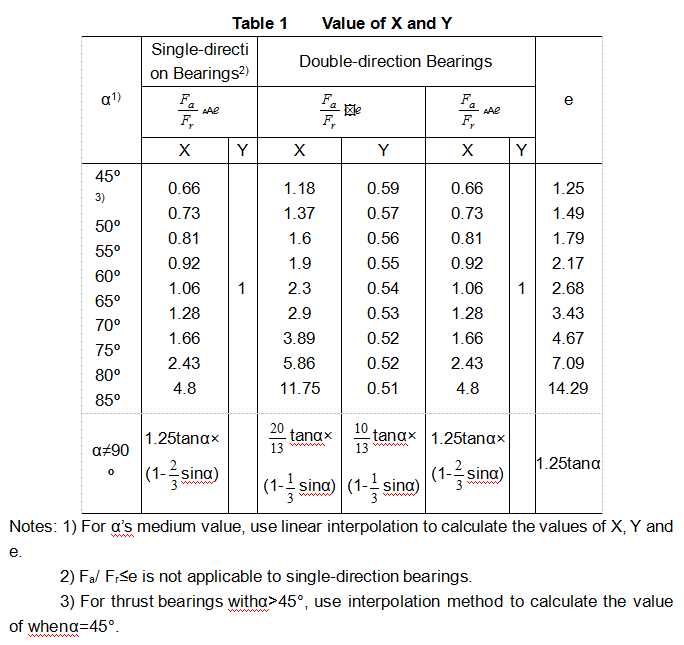
Whenα≠90, acted by constant and invariable radial and axial loads, the dynamic equivalent axial load is: Pa=XFr+YFa
See Annex Table 1 for the coefficients of X and Y.
Static equivalent axial load
Whenα=90°, the static equivalent axial load is: P0a=Fa;
Whenα≠90°, the static equivalent axial load is: P0a=2.3Frtanα+Fa.
Where: For double-direction bearings, this equation is applicable to the status when the ration of radial load and axial load is an arbitrary value; for single-direction bearings, when Fr/Fa≤0.44ctgα, the equation is reliable; when, the Fr/Fa>0.67ctgα, the equation can still give satisfactory P0a value, but not very conservative.
